

مدتی بود که دنبال یک مدار شارژر برای باطری های سیلد اسید میگشتم که کاربرد عمومی داشته باشد و بشود با هر ولتاژی باطری را شارژ کرد .
توی سایت www.eleccircuit.com مدار زیر را معرفی کرده بود
http://www.eleccircuit.com/modify-ol...scr-and-ca723/
This is how to modify old Lead-acid battery charger or convert power supply to automatic battery charger form. To protect battery over charging.
We use simple circuit with comparator circuit by CA723 regulator and power SCR cut off current controller.
The working principle
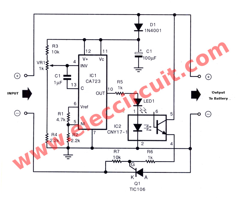
As Figure 1 is circuit diagram of this project. The charging and stop charging of this circuit will check voltage drop across the battery. If voltage across less than 13.8 volts. The circuit will begin charging, but voltage across rises to 14.4 volts. The circuit will stop automatically.
When battery is fully charged. The circuit will stop since voltage across the battery too high. That is ?he voltage across the battery Are equal to the input voltage. The voltage comparator circuit internal IC1 will acts to stop the Q1. The adjustment voltage regular of IC1 will get voltage through the diode-D1 which is applied current about 10 mA.
Then the reference voltage divider circuit inside IC1 will get to dividing the voltage down to 2.2 volts. by R1 and R2. Which this reference voltage will be compared with the battery voltage that is adjusted from VR1.
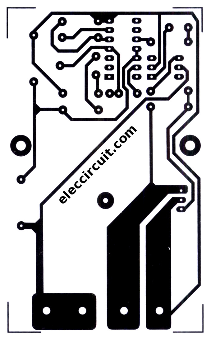
Figure 1 The circuit diagram of automatic battery charger using 723-IC and SCR
If the voltage of the battery is low, output pin 10 of IC1 is a logic level is “1”. Make LED1 light ready the working of optocoupler of IC2. To connect the power motivate SCR, to work as the operation of optocoupler-IC2. It would have current to recharging the battery.
Which this Q1 also acts as control Amount of charging current. When voltage at the battery higher up will cause voltage across the SCR (Q1) between cathode and anode lead no different. That meant have voltage is zero volts. Making Q1 stop conducting current is stop charging and will start recharging, when Q1 conduct current again because the battery voltage lower than 13.8 volts.
The voltage detection of battery and the recharging will detected voltage across Q1 or the differences of voltage at cathode and anode lead and adjusted charging level at 14.4 volts to offset be lose inside Q1 about 1 volts
How to builds
This project not hard over your try. You can assemble them on universal board. Figure 2 is PCB layout and Figure 3 is components layout of this project
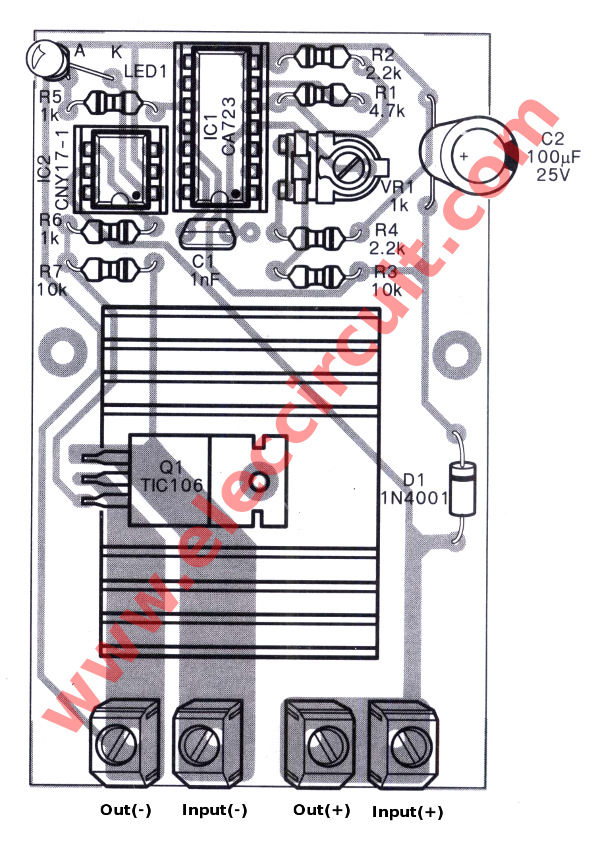
Figure 3
Customization and deployment.
To begin with apply the battery you need charging in circuit, secondly, apply voltage of 13.8-14.4 volts to input of this circuit. Then use voltmeter to measure voltage across battery. To check voltage if it is lower than 13.8 volts we will don’t see LED1 glow.
Next, rotate VR1 in left slowly until see LED1 glow. It is shown that ready the circuit start charging to the battery. The voltage across battery have voltage rise up to 13.8V. Then rotate slowly VR1 to right until LED1 go out. That is stop charging and automatically working between charging and discharging, now ready to using. This circuit can apply charging current to 1 A and maximum 5 A.
The parts you need
Resistors size ¼W +-5%
R1___________4.7K
R2, R4________2.2K
R3, R7________10K
R5, R6________1K
potentiometer
VR1__________1K
Capacitors
C1_____1nF polyester
C2_____100uF/25V Electrolytic.
Semiconductors
LED1__LED as you want 3 mm.
D1_____1N4001____1A 50V Didoe
IC1_____CA723 DC regulator IC
IC2_____CNY171-1
SCR1____TIC106 power SCR 5A 400V
Others Heatsink,Socket,PCB, etc.
اطلاعات الکترونیک من در حدی نیست که بتوانم تغییرات مطمئنی در مدار ایجاد ممنون میشم دوستانی که توانایی دارند در خصوص سوالهای زیر من را راهنمایی کنند
1-آیا میشود با ایجاد تغیییراتی در این مدار با ولتاژهای ورودی 5 و 12 و 15.5 ولت ( ولتاژ ورودی اتومات بین 5 تا 16 ولت ) بتواند ولتاژ 14.4 مورد نیاز برای شارژ باطری سیلد اسید را تامین کند ؟
2- در صورت مثبت بودن جواب آیا هر بار باید پتانسومتر VR1 را برای هر ولتاژ ورودی دوباره تنظیم کرد ؟
3- به نظر شما آیا مدار مطمئنی هست که بشه برای مدت طولانی از آن استفاده کرد ؟
از کمک و راهنمایی شما سپاسگذارم
توی سایت www.eleccircuit.com مدار زیر را معرفی کرده بود
http://www.eleccircuit.com/modify-ol...scr-and-ca723/
This is how to modify old Lead-acid battery charger or convert power supply to automatic battery charger form. To protect battery over charging.
We use simple circuit with comparator circuit by CA723 regulator and power SCR cut off current controller.
The working principle
As Figure 1 is circuit diagram of this project. The charging and stop charging of this circuit will check voltage drop across the battery. If voltage across less than 13.8 volts. The circuit will begin charging, but voltage across rises to 14.4 volts. The circuit will stop automatically.
When battery is fully charged. The circuit will stop since voltage across the battery too high. That is ?he voltage across the battery Are equal to the input voltage. The voltage comparator circuit internal IC1 will acts to stop the Q1. The adjustment voltage regular of IC1 will get voltage through the diode-D1 which is applied current about 10 mA.
Then the reference voltage divider circuit inside IC1 will get to dividing the voltage down to 2.2 volts. by R1 and R2. Which this reference voltage will be compared with the battery voltage that is adjusted from VR1.
Figure 1 The circuit diagram of automatic battery charger using 723-IC and SCR
If the voltage of the battery is low, output pin 10 of IC1 is a logic level is “1”. Make LED1 light ready the working of optocoupler of IC2. To connect the power motivate SCR, to work as the operation of optocoupler-IC2. It would have current to recharging the battery.
Which this Q1 also acts as control Amount of charging current. When voltage at the battery higher up will cause voltage across the SCR (Q1) between cathode and anode lead no different. That meant have voltage is zero volts. Making Q1 stop conducting current is stop charging and will start recharging, when Q1 conduct current again because the battery voltage lower than 13.8 volts.
The voltage detection of battery and the recharging will detected voltage across Q1 or the differences of voltage at cathode and anode lead and adjusted charging level at 14.4 volts to offset be lose inside Q1 about 1 volts
How to builds
This project not hard over your try. You can assemble them on universal board. Figure 2 is PCB layout and Figure 3 is components layout of this project
Figure 3
Customization and deployment.
To begin with apply the battery you need charging in circuit, secondly, apply voltage of 13.8-14.4 volts to input of this circuit. Then use voltmeter to measure voltage across battery. To check voltage if it is lower than 13.8 volts we will don’t see LED1 glow.
Next, rotate VR1 in left slowly until see LED1 glow. It is shown that ready the circuit start charging to the battery. The voltage across battery have voltage rise up to 13.8V. Then rotate slowly VR1 to right until LED1 go out. That is stop charging and automatically working between charging and discharging, now ready to using. This circuit can apply charging current to 1 A and maximum 5 A.
The parts you need
Resistors size ¼W +-5%
R1___________4.7K
R2, R4________2.2K
R3, R7________10K
R5, R6________1K
potentiometer
VR1__________1K
Capacitors
C1_____1nF polyester
C2_____100uF/25V Electrolytic.
Semiconductors
LED1__LED as you want 3 mm.
D1_____1N4001____1A 50V Didoe
IC1_____CA723 DC regulator IC
IC2_____CNY171-1
SCR1____TIC106 power SCR 5A 400V
Others Heatsink,Socket,PCB, etc.
اطلاعات الکترونیک من در حدی نیست که بتوانم تغییرات مطمئنی در مدار ایجاد ممنون میشم دوستانی که توانایی دارند در خصوص سوالهای زیر من را راهنمایی کنند
1-آیا میشود با ایجاد تغیییراتی در این مدار با ولتاژهای ورودی 5 و 12 و 15.5 ولت ( ولتاژ ورودی اتومات بین 5 تا 16 ولت ) بتواند ولتاژ 14.4 مورد نیاز برای شارژ باطری سیلد اسید را تامین کند ؟
2- در صورت مثبت بودن جواب آیا هر بار باید پتانسومتر VR1 را برای هر ولتاژ ورودی دوباره تنظیم کرد ؟
3- به نظر شما آیا مدار مطمئنی هست که بشه برای مدت طولانی از آن استفاده کرد ؟
از کمک و راهنمایی شما سپاسگذارم


 oo:
oo:
دیدگاه