

سلام
من این کد رو در پروتئوس تست کردم درست کار می کنه ولی در عمل خیر
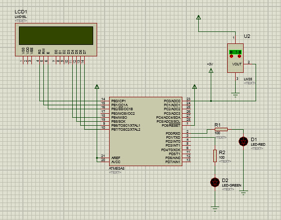
من در عمل از یک میکرو مگا8 و یک ال سی دی استفاه کردم و دو عدد ال ای دی که با دما بالاوپایین شدن مثلا قرمز و سبز روشن بشه با شرطی که گذاشتم .
من این کد رو در پروتئوس تست کردم درست کار می کنه ولی در عمل خیر
من در عمل از یک میکرو مگا8 و یک ال سی دی استفاه کردم و دو عدد ال ای دی که با دما بالاوپایین شدن مثلا قرمز و سبز روشن بشه با شرطی که گذاشتم .
کد:
/*****************************************************
This program was produced by the
CodeWizardAVR V2.05.3 Standard
Automatic Program Generator
© Copyright 1998-2011 Pavel Haiduc, HP InfoTech s.r.l.
http://www.hpinfotech.com

Project :
Version :
Date  : 07/04/2015
Author : PerTic@n
Company : If You Like This Software,Buy It
Comments:


Chip type        : ATmega8
Program type      : Application
AVR Core Clock frequency: 8.000000 MHz
Memory model      : Small
External RAM size    : 0
Data Stack size     : 256
*****************************************************/

#include <mega8.h>

#include <delay.h>
 #include <stdlib.h>
// Alphanumeric LCD functions
#include <alcd.h>

#define ADC_VREF_TYPE 0x00

// Read the AD conversion result
unsigned int read_adc(unsigned char adc_input)
{
ADMUX=adc_input | (ADC_VREF_TYPE & 0xff);
// Delay needed for the stabilization of the ADC input voltage
delay_us(10);
// Start the AD conversion
ADCSRA|=0x40;
// Wait for the AD conversion to complete
while ((ADCSRA & 0x10)==0);
ADCSRA|=0x10;
return ADCW;
}

// Declare your global variables here
 char s[10];
 int d,vol;
void main(void)
{
// Declare your local variables here

// Input/Output Ports initialization
// Port B initialization
// Func7=In Func6=In Func5=In Func4=In Func3=In Func2=In Func1=In Func0=In
// State7=T State6=T State5=T State4=T State3=T State2=T State1=T State0=T
PORTB=0x00;
DDRB=0x00;

// Port C initialization
// Func6=In Func5=In Func4=In Func3=In Func2=In Func1=In Func0=In
// State6=T State5=T State4=T State3=T State2=T State1=T State0=T
PORTC=0x00;
DDRC=0x00;

// Port D initialization
// Func7=Out Func6=Out Func5=Out Func4=Out Func3=Out Func2=Out Func1=Out Func0=Out
// State7=0 State6=0 State5=0 State4=0 State3=0 State2=0 State1=0 State0=0
PORTD=0x00;
DDRD=0xFF;

// Timer/Counter 0 initialization
// Clock source: System Clock
// Clock value: Timer 0 Stopped
TCCR0=0x00;
TCNT0=0x00;

// Timer/Counter 1 initialization
// Clock source: System Clock
// Clock value: Timer1 Stopped
// Mode: Normal top=0xFFFF
// OC1A output: Discon.
// OC1B output: Discon.
// Noise Canceler: Off
// Input Capture on Falling Edge
// Timer1 Overflow Interrupt: Off
// Input Capture Interrupt: Off
// Compare A Match Interrupt: Off
// Compare B Match Interrupt: Off
TCCR1A=0x00;
TCCR1B=0x00;
TCNT1H=0x00;
TCNT1L=0x00;
ICR1H=0x00;
ICR1L=0x00;
OCR1AH=0x00;
OCR1AL=0x00;
OCR1BH=0x00;
OCR1BL=0x00;

// Timer/Counter 2 initialization
// Clock source: System Clock
// Clock value: Timer2 Stopped
// Mode: Normal top=0xFF
// OC2 output: Disconnected
ASSR=0x00;
TCCR2=0x00;
TCNT2=0x00;
OCR2=0x00;

// External Interrupt(s) initialization
// INT0: Off
// INT1: Off
MCUCR=0x00;

// Timer(s)/Counter(s) Interrupt(s) initialization
TIMSK=0x00;

// USART initialization
// USART disabled
UCSRB=0x00;

// Analog Comparator initialization
// Analog Comparator: Off
// Analog Comparator Input Capture by Timer/Counter 1: Off
ACSR=0x80;
SFIOR=0x00;

// ADC initialization
// ADC Clock frequency: 125.000 kHz
// ADC Voltage Reference: AREF pin
ADMUX=ADC_VREF_TYPE & 0xff;
ADCSRA=0x86;

// SPI initialization
// SPI disabled
SPCR=0x00;

// TWI initialization
// TWI disabled
TWCR=0x00;

// Alphanumeric LCD initialization
// Connections are specified in the
// Project|Configure|C Compiler|Libraries|Alphanumeric LCD menu:
// RS - PORTB Bit 0
// RD - PORTB Bit 1
// EN - PORTB Bit 2
// D4 - PORTB Bit 4
// D5 - PORTB Bit 5
// D6 - PORTB Bit 6
// D7 - PORTB Bit 7
// Characters/line: 12
lcd_init(12);
lcd_gotoxy(0,0);
              lcd_putsf("salam");
              delay_ms(1000);
              lcd_clear();

while (1)
   {
   d=read_adc(0);
   vol=(5*d)/1023;
      itoa(vol,s);
      lcd_gotoxy(0,0);
      lcd_puts(s);
           if(s>50)
           {
         PORTD.0=1;
         }
         if(s<50)
         {
         PORTD.1=0;
         }


   }
}


 ; //پیام خوش آمد گویی و شروع با نام خدا
دیدگاه