

سلام یه نگاهی به زیر بندازید ببینید چیزی دستگیرتون میشه من ساختم ولی نشََََـــــــــــــد چرا؟
Using EasyHDL with ISIS can be a little bit sticky because of the lack of documentation for this language.
In this tutorial, i’m starting from scratch with my own little experience and discoveries i’ve made.
First, EasyHDL is a variation of the HDL language (VERILOG).
Its BASIC-like oriented syntax.
It can be usefull to simulate simple or complex behaviors of schematic models that are not included in ISIS libraries.
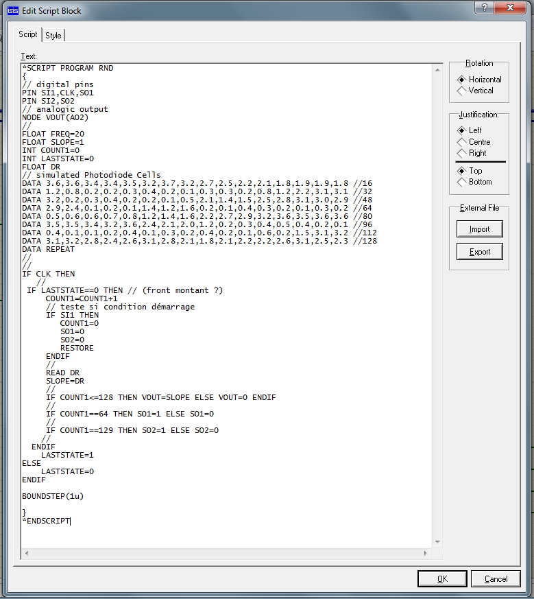
For this Tutorial, we will simulate a simple behavior of a cell-array sensor known as TSL202R.
The TSL202R is a 128 photodiodes array organised in 1 row.
If you take a look at the datasheet, you’ll see that, actually, the sensor’s cells are splitted into 2 sections of 64 photodiodes each, than can be cascaded
to form a unique row of 128, by correctly connecting the input/output pins of the internal shift register.
For ease of simulation, this easyHDL tutorial will simulate the device in cascaded mode, wich means that the analogue output will be AO2 pin,SO2
(’end of cell 128 output&rsquo , while the inputs of the device will be CLK and SI1 pins.
Despite that fact, SO1 (’end of 64cells output’ signal) will be available as an useable output.
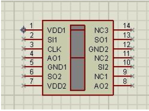
Starting from the device’s datasheet, the first thing is to build the graphical object into ISIS, with Pins numbered and named accordingly to the datas
( VDD,SO1,SO2,SI1,SI2,CLK,AO1,AO2,GND )
Just before selecting ‘make device’ from the right-click menu, it should look like this :
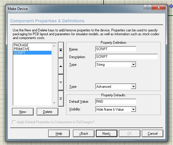
Now, when making device, you have to Add properties/definitions to the device, in order to specify wether the simulator will have to treat it as analogic
or digital when simulating.
For this tutorial, the script will act as analog, because the AO outputs of the TSL202R are analogic levels.
The Device will have 3 properties :
Package : you can let it blank, or add one (DIL14 like)
PRIMITIVE : ANALOG
SCRIPT : default value can be the easyHDL script’s name you want to be associated with the device.
Notice that the SCRIPT property is NOT listed in the drop-down menu of the device’s properties et definition’s popup window.Select ‘blank item’ to
add this property (name : SCRIPT )
The PRIMITIVE property setup (default value : ANALOG ):
Using EasyHDL with ISIS can be a little bit sticky because of the lack of documentation for this language.
In this tutorial, i’m starting from scratch with my own little experience and discoveries i’ve made.
First, EasyHDL is a variation of the HDL language (VERILOG).
Its BASIC-like oriented syntax.
It can be usefull to simulate simple or complex behaviors of schematic models that are not included in ISIS libraries.
For this Tutorial, we will simulate a simple behavior of a cell-array sensor known as TSL202R.
The TSL202R is a 128 photodiodes array organised in 1 row.
If you take a look at the datasheet, you’ll see that, actually, the sensor’s cells are splitted into 2 sections of 64 photodiodes each, than can be cascaded
to form a unique row of 128, by correctly connecting the input/output pins of the internal shift register.
For ease of simulation, this easyHDL tutorial will simulate the device in cascaded mode, wich means that the analogue output will be AO2 pin,SO2
(’end of cell 128 output&rsquo
, while the inputs of the device will be CLK and SI1 pins.Despite that fact, SO1 (’end of 64cells output’ signal) will be available as an useable output.
Starting from the device’s datasheet, the first thing is to build the graphical object into ISIS, with Pins numbered and named accordingly to the datas
( VDD,SO1,SO2,SI1,SI2,CLK,AO1,AO2,GND )
Just before selecting ‘make device’ from the right-click menu, it should look like this :
Now, when making device, you have to Add properties/definitions to the device, in order to specify wether the simulator will have to treat it as analogic
or digital when simulating.
For this tutorial, the script will act as analog, because the AO outputs of the TSL202R are analogic levels.
The Device will have 3 properties :
Package : you can let it blank, or add one (DIL14 like)
PRIMITIVE : ANALOG
SCRIPT : default value can be the easyHDL script’s name you want to be associated with the device.
Notice that the SCRIPT property is NOT listed in the drop-down menu of the device’s properties et definition’s popup window.Select ‘blank item’ to
add this property (name : SCRIPT )
The PRIMITIVE property setup (default value : ANALOG ):

 oo:
oo:


دیدگاه